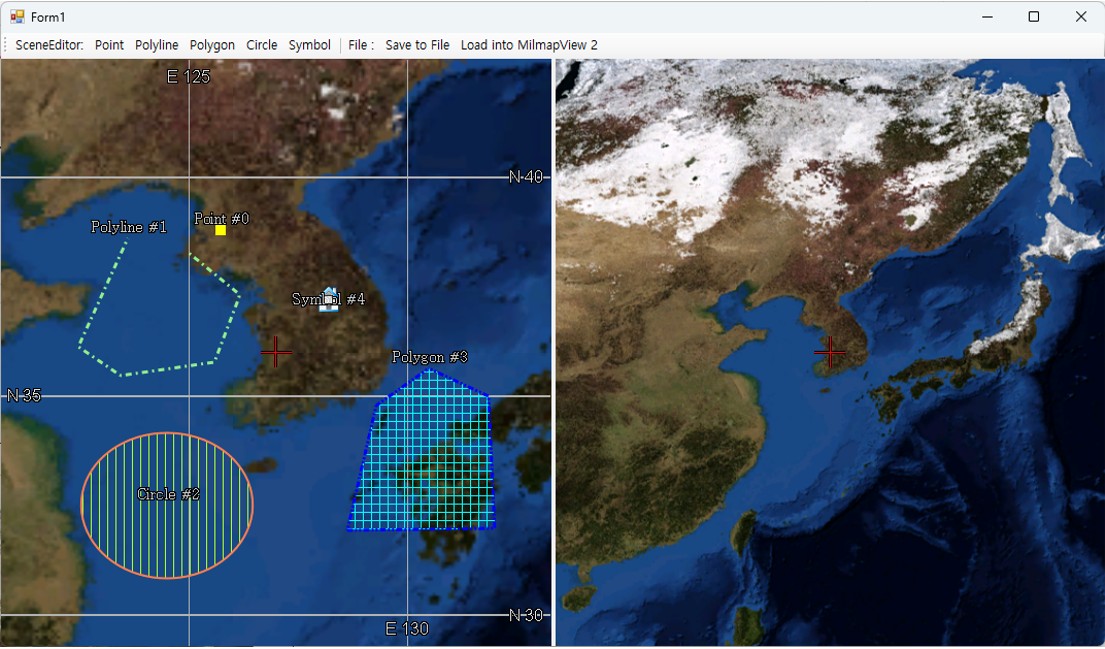
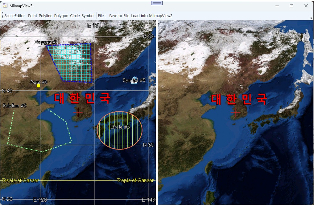
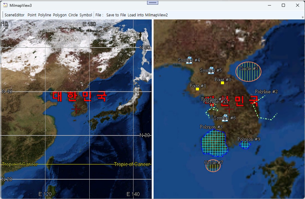
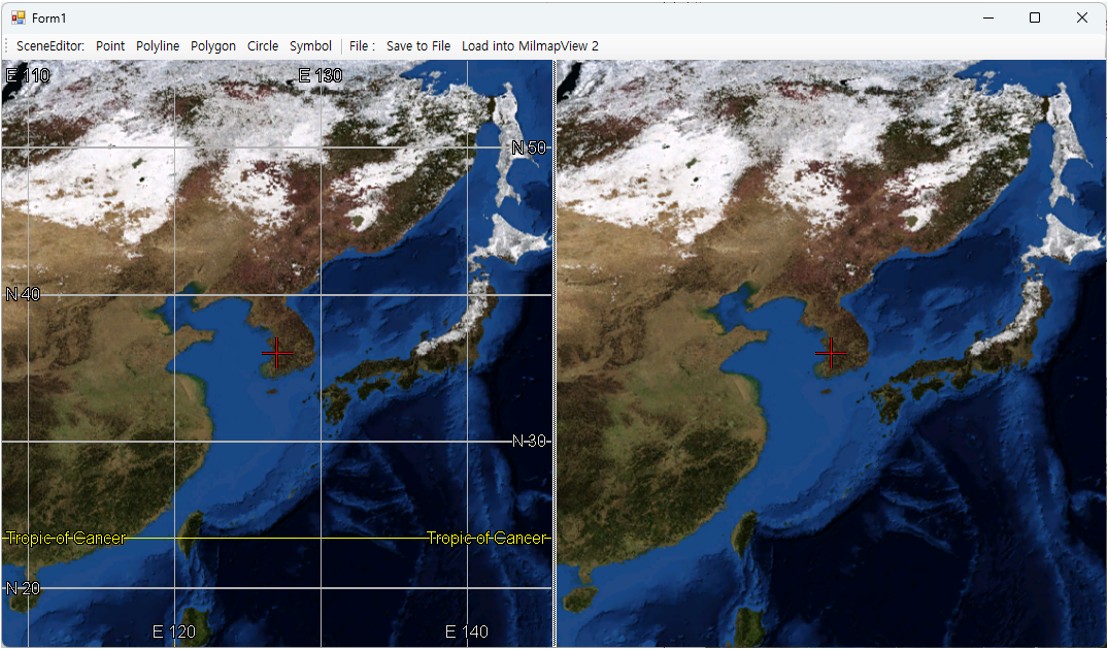
Pixoneer.NXDL.NSCENE의 다양한 scene 객체를 생성/편집하는 방법을 알아보고, NXMilmapLayerSceneEditor와 NXMilmapLayerSceneDisplay 레이어를 이용하여 MilmapView에서 scene 객체를 다루는 방법을 구현해 보도록 합니다
이를 위해 두 개의 NXMilmapView로 구성하여 하나의 View에는 NXMilmapLayerSceneEditor를 추가하고 나머지 View에는 NXMilmapLayerSceneDisplay를 추가합니다. NXMilmapLayerSceneEditor가 추가된 MilmapView 위에서 Scene 객체를 추가하고 편집한 뒤 파일로 저장하고 이를
NXMilmapLayerSceneDisplay에 로딩하여 도시합니다.
들어가기 전에
설치 프로그램으로 배포되는 XDL 엔진은 Visual Studio 2022 x64 Release 버전으로, Visual Studio 2022 이상의 버전에서 사용 가능하다.
아래의 설명은 Visual Studio 2022를 기준으로 하겠다.
// Form1.cs

using Pixoneer.NXDL;
using Pixoneer.NXDL.NXMilmap;
using Pixoneer.NXDL.NSCENE;

namespace XDL_MilmapView3
{
    public partial class Form1 : Form
    {
        public Form1()
        {
            InitializeComponent();

            nxSceneLayerDisplay = new NXMilmapLayerSceneDisplay();
            nxSceneLayerEditor = new NXMilmapLayerSceneEditor();


…
3.2 Form1의 Load 이벤트 함수에서 nxSceneLayerDisplay와 nxSceneLayerEditor를 nxMilmapView2와 nxMilmapView1에 각각 추가하고 화면 중심을 설정한다. 본 예제에서는 nxMilmapView1에서는 Degree 형식의 grid가 도시되도록 설정한다.
C#
private void Form1_Load(object sender, EventArgs e)
{
    nxSceneLayerEditor.AttachTo(nxMilmapView1);
    nxSceneLayerDisplay.AttachTo(nxMilmapView2);

    // XMilmapConfig.xml을 이용하여 군사지도를 위한 NXMilmapView 및 NXMilmapEngine을 초기화한다.
    if (!NXMilmapView.m_MapEngine.InitFromXML("c:\\Pixoneer\\Xdl3.0\\Config\\XMilmapConfig.xml"))
    {
        return;
    }

    // 마우스 휠을 끌고 당기는 것을 확대/축소 요인으로 계산하여 화면을 확대/축소한다.
    // 이 때, 계산된 공간 해상도와 가까운 축척(scale)이 있는 경우 자동적으로 해당 축척으로 바뀌면서 도시된다.
    // 마우스 휠을 끌고 당기는 것으로 화면의 축척을 변경하려면, NXMilmapView.eWheelZoomAction.ByScaleIndex으로 설정
    nxMilmapView1.WheelZoomAction = NXMilmapView.eWheelZoomAction.ByZoomFactor;
    nxMilmapView1.SetGeoToCenter(0, new XVertex2d(127.0, 36.0));

    nxMilmapView2.WheelZoomAction = NXMilmapView.eWheelZoomAction.ByZoomFactor;
    nxMilmapView2.SetGeoToCenter(0, new XVertex2d(127.0, 36.0));

    nxMilmapView1.ShowGrid = true;
    nxMilmapView1.GridType = NXMilmapView.eGridType.GridDegrees;
}
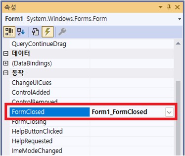
3.3 Form1의 Closed 이벤트(FormClosed) 함수를 생성하여 Milmap 관련 해제와 scene 객체 메모리 해지를 위해 코드를 추가한다.
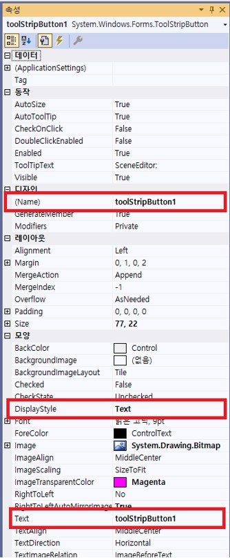
3.4 Scene 객체를 추가하기 위한 ToolStripButton인 pointToolStripButton, polylineToolStripButton, polygonToolStripButton, circleToolStripButton, symbolToolStripButton을 선택한 뒤 각각 더블 클릭하여 Click 이벤트 함수를 추가한다.
pointToolStripButton의 경우 아래 그림과 같이 pointToolStripButton_Click 함수가 추가된다.
3.5 Scene 객체 추가 이벤트 함수에 nxSceneLayerEditor에 새로운 scene 객체를 생성하도록 요청하는 코드를 구현한다.
NXMilmapLayerSceneEditor의 CreateNewOBJ를 통해 매개변수에 따른 scene 객체를 생성하여 추가 및 편집 과정을 진행한다. CreatNewOBJ에 입력값은 scene 객체의 클래스 이름이다. Point, polyline, polygon, circle, symbol의 객체 추가 코드는 아래와 같다.
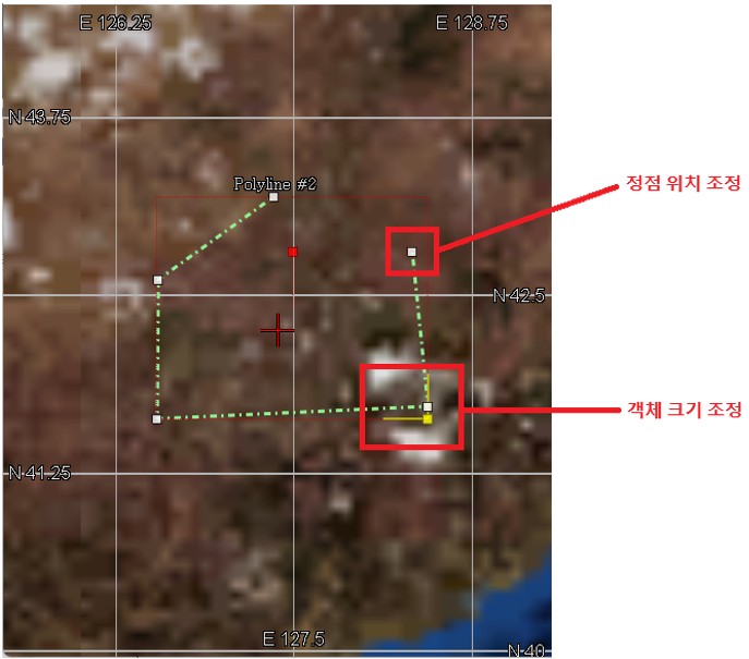
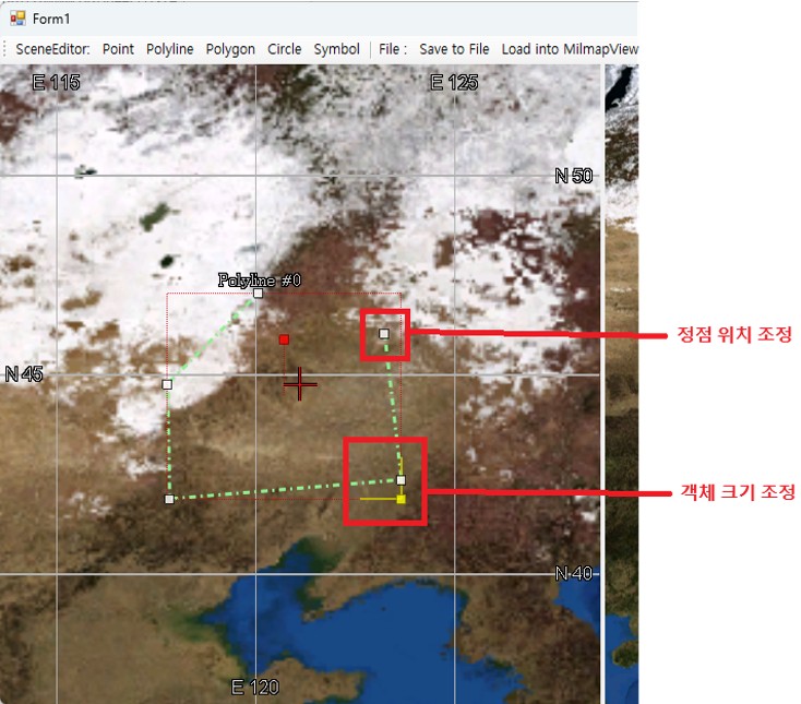
ToolStrip 중 “Polyline”을 선택한 후 프로그램의 Grid가 도시된 MilmapView에서 마우스 왼쪽 버튼을 클릭하고 마우스를 움직이면 생성된 Polyline을 확인할 수 있으며 2점 이상이 되면 “No named XscPolyLine” 이라는 이름과 함께 도시되는 것을 볼 수 있다.
정점을 추가하는 것은 마우스 왼쪽 버튼을 클릭하면 되고, 생성 작업을 종료하려면 마우스 왼쪽 버튼을 더블 클릭하면 된다. 생성작업을 종료하면 아래와 같이 객체의 정점 위치 조정, 크기 조정을 할 수 있는 컨트롤들을 확인할 수 있다.
각 객체는 기본 도시 속성정보를 이용하여 생성된다. Symbol의 경우,
을 기본값으로 하여 생성된다.
3.7nxSceneLayerEditor에 OnObjectCreated 이벤트를 추가하여 XDL 엔진 내부에서 객체 생성 완료 시점에 각 객체에 대한 도시 속성을 변경해 본다.
nxSceneLayerEditor 생성자 다음에 아래와 같이 OnObjectCreated 이벤트를 추가한다.
C#
namespace XDL_MilmapView3
{
    public partial class Form1 : Form
    {
        public Form1()
        {
            InitializeComponent();

            nxSceneLayerDisplay = new NXMilmapLayerSceneDisplay();
            nxSceneLayerEditor = new NXMilmapLayerSceneEditor();
            nxSceneLayerEditor.OnObjectCreated += new NXSCEditEvent(nxSceneLayerEditor_OnObjectCreated);
        }
…
nxSceneLayerEditor_OnObjectCreated 함수에 아래와 같이 도시 속성 코드를 추가한다.
C#
bool nxSceneLayerEditor_OnObjectCreated(XscObj pObj)
{
    if (pObj == null) return false;

    // Scene 객체의 클래스 이름 가져오기
    string typeName = pObj.GetTypeName();
    if (typeName == "XscPoint")
    {
        XscPoint objPoint = (XscPoint)pObj;
        objPoint.LineColor = Color.Yellow;
        // Point의 크기
        objPoint.LineWidth = 10;
        // PointType으로는 Cross, Dot, Triangle, Rect, X가 있다.
        objPoint.PointType = XscPoint.ePointType.Rect;
        objPoint.Name = "Point #" + objPoint.ObjID.ToString();
    }
    else if (typeName == "XscPolyLine")
    {
        XscPolyLine objPolyLine = (XscPolyLine)pObj;
        objPolyLine.LineColor = Color.LightGreen;
        objPolyLine.LinePattern = XscLinePattern.eLinePatternType.DashDot;
        objPolyLine.LineWidth = 3;
        objPolyLine.Name = "Polyline #" + objPolyLine.ObjID.ToString();
    }
    else if (typeName == "XscPolygon")
    {
        XscPolygon objPolygon = (XscPolygon)pObj;
        objPolygon.BorderColor = Color.Blue;
        objPolygon.BorderSize = 3;
        objPolygon.LinePattern = XscLinePattern.eLinePatternType.DashDotDot;
        objPolygon.FillColor = Color.Cyan;
        // FillPattern이 Solid가 아닌 경우에는 배경색이 투명하게 처리된다.
        objPolygon.FillPattern = XscFillPattern.eFillPatternType.Cross;
        objPolygon.Name = "Polygon #" + objPolygon.ObjID.ToString();
    }
    else if (typeName == "XscCircle")
    {
        XscCircle objCircle = (XscCircle)pObj;
        objCircle.LineColor = Color.Coral;
        objCircle.LineWidth = 2;
        objCircle.FillColor = Color.GreenYellow;
        objCircle.FillPattern = XscFillPattern.eFillPatternType.Vertical;
        objCircle.Name = "Circle #" + objCircle.ObjID.ToString();
    }
    else if (typeName == "XscSymbol")
    {
        XscSymbol objSymbol = (XscSymbol)pObj;
        // DefaultSymbolName으로 사용할 수 있는 것은
        // Apartment, Image, Model, Public, Stadium, TextChart가 있다.
        // 이는 XDL 엔진 설치 폴더 중 Resource\Scenes\Icons에 저장되어 있다.
        // 사용자 정의의 심볼을 로딩하고자 한다면, DefaultSymbolName 대신
        //  UserSymbolPath 속성으로 경로를 설정한다.
        objSymbol.DefaultSymbolName = "Apartment";
        objSymbol.UpdateSymbol();
        objSymbol.Name = "Symbol #" + objSymbol.ObjID.ToString();
    }

    nxMilmapView1.RefreshScreen();
    return default(bool);
}
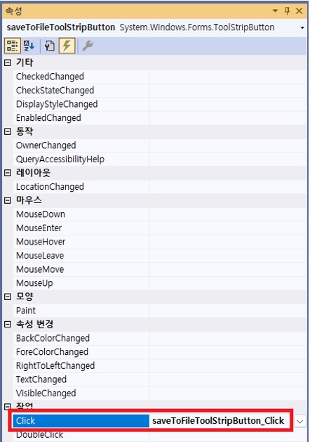
3.8nxMilmapView1에 생성한 scene 객체를 파일로 저장하기 위해 ToolStrip의 saveToFileToolStripButton을 더블 클릭하여 이벤트함수를 추가하고 코드를 구현한다.
마우스로 더블 클릭하면 “Click”에 대한 이벤트 함수가 자동 추가된다.
nxSceneEditor의 XScene 객체를 얻어 파일로 저장한다. XDL 엔진의 Scene 파일은 SML을 확장자로 하는 XML 파일이다. 코드는 아래와 같다.
C#
private void saveToFileToolStripButton_Click(object sender, EventArgs e)
{
    // 생성한 scene 객체를 가지고 있는 최상위 XScene 객체를 얻어온다.
    XScene sceneRoot = nxSceneLayerEditor.GetScene();
    if (sceneRoot == null) return;

    // 저장을 위한 FileDialog 생성
    SaveFileDialog saveDlg = new SaveFileDialog();
    saveDlg.Filter = "XDL Scene file(*.sml)|*.sml;||";
    if (saveDlg.ShowDialog() != DialogResult.OK) return;

    // 파일경로에 XScene 객체의 데이터를 XML 형태로 저장한다.
    // 세 번째 매개변수인 XSpatialReference는 출력 좌표계 정보를 설정하는 것으로서,
    // 여기에서는 XScene 객체의 좌표계 정보로 하겠다.
    if (XScene.SaveScene(sceneRoot, saveDlg.FileName, sceneRoot.SR))
    {
        MessageBox.Show("MilmapView의 scene 객체를 파일로 저장하였습니다.");
    }
    else
    {
        MessageBox.Show("MilmapView의 scene 객체를 파일로 저장하지 못했습니다.");
    }
}
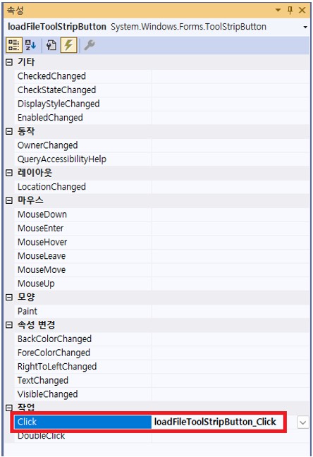
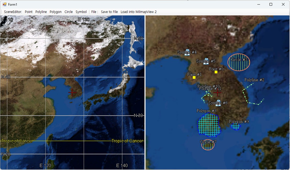
3.9Scene 파일인 SML 파일을 선택하여 scene 객체를 생성하지 않은 다른 MilmapView 환경에 도시하도록 한다. 이를 위한 loadFileToolStripButton을 더블 클릭하여 Click 이벤트함수를 추가하고 파일을 로딩하는 코드를 추가한다.
마우스로 더블 클릭하면 “Click”에 대한 이벤트 함수가 자동 추가된다.
SML 파일을 NXMilmapLayerSceneDispaly의 Open 함수를 이용하여 로딩하면 NXMilmapLayerSceneDisplay의 scene 데이터가 파일의 내용으로 갱신된다. 본 예제에서는 NXMilmapLayerSceneDisplay 변수인 nxSceneLayerDisplay의 Open 함수를 통해 SML 파일을 로딩한 후 XScene 객체를 얻어서
도시 순서를 설정한다. XScene에 추가된 scene 객체를 추가된 순서대로 도시하고자 하면, XScene 객체를 얻어 DisplayOrder를 OrderByAddSequence로 수정한다. XScene의 DisplayOrder 기본값은 OrderNone으로, OrderNone, OrderByAddSequence, OrderByUserSequence가 있다.
코드는 아래와 같다.
C#
private void loadFileToolStripButton_Click(object sender, EventArgs e)
{
    // 파일을 선택하기 위해서 FileDialog 생성
    OpenFileDialog openDlg = new OpenFileDialog();
    openDlg.Filter = "XDL Scene file(*.sml)|*.sml;||";
    if (openDlg.ShowDialog() != DialogResult.OK) return;

    // NXPlanetLayerSceneDisplay의 Open 함수를 이용하여 scene 객체 로딩
    if (nxSceneLayerDisplay.Open(openDlg.FileName))
    {
        XScene scene = nxSceneLayerDisplay.GetScene();
        // Scene 객체 도시 방법을 추가되는 순서대로 도시하도록 설정한다.
        // 기본값은 XScene.eDisplayOrder.OrderNone이다.
        scene.DisplayOrder = XScene.eDisplayOrder.OrderByAddSequence;

        MessageBox.Show("MilmapView의 scene 객체를 갱신하겠습니다");
        nxMilmapView2.RefreshScreen();
    }
    else
    {
        MessageBox.Show("scene 파일을 로딩할 수 없습니다.");
    }
}
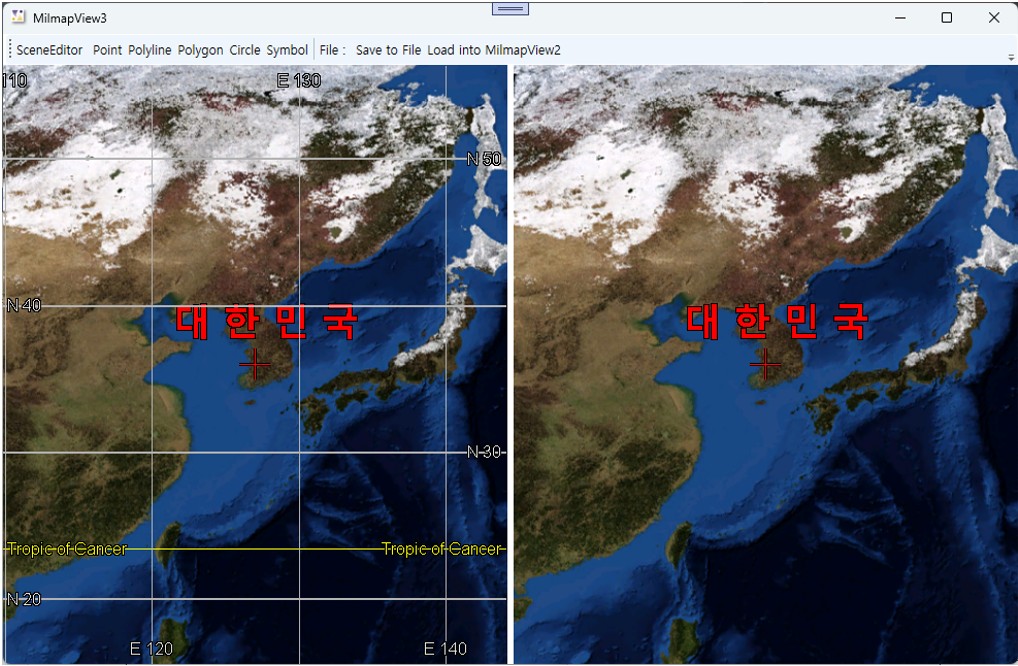
3.10솔루션을 빌드하고 실행한다.
샘플 프로젝트와 함께 배포된 파일인 test.sml 파일을 로딩해 본다.
1기본 프로그램 작성
1.1Visual Studio 2022를 이용하여 예제 XDL MilmapView 활용 첫번째의
기본 프로그램 작성
부분을 참고로 기본 프로젝트를 생성한다.
프로젝트 이름은 “XDL_MilmapView3”로 한다.
1.2 Pixoneer.NXDL.NSCENE을 이용하기 위해서 “NXDLscene.dll”을 프로젝트의 참조로 추가한다.
참조 추가 방법은 XDL MilmapView 활용 첫번째 기본 프로그램 작성의
참조추가
부분을 참고한다.
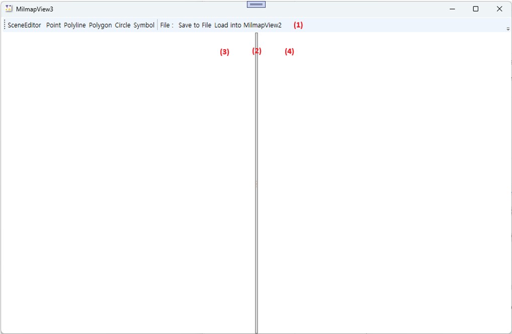
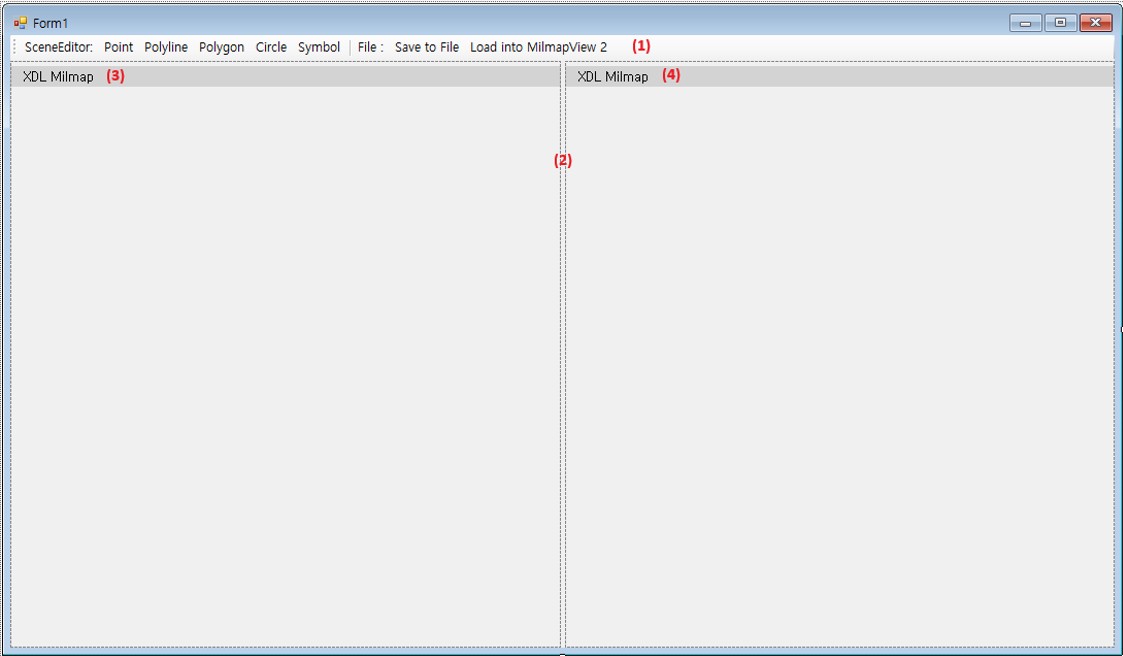
2프로그램 디자인
Number
Name
Control type
(1)
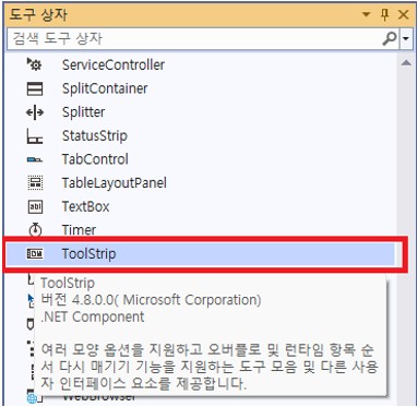
toolStrip1
ToolBar
(2)
splitContainter1
GridSplitter
(3)
nxMilmapView1
NXMilmapView
(4)
nxMilmapView2
NXMilmapView
2.1 (1)에 ToolBar와 Button 컨트롤을 사용하여 메뉴를 구성한다. MainWindow.xaml 창에서 기본으로 생성된 Grid 레이아웃에 Grid.RowDefinition을 이용하여 두 개의 Row을 생성한다. 첫 번째 Row에는 Toolbar를 배치한다(1). 두 번째 Row에서는 세 개의 Column으로 나누어 두 개의
NXMilmapView 컨트롤(3), (4)과 한 개의 GridSplitter(2)을 배치할 것이다.
2.2 두 번째 Grid를 세 개의 Column으로 나눈 뒤 첫 번째 Column에는 MilmapView 컨트롤을 올리고 이름을 nxMilmapView1라고 명명한다(3). 두 번째 Column에 GridSplitter을 배치한다(2). 세 번째 Column에는 MilmapView 컨트롤을 올리고 이름을 nxMilmapView2라고 정의한다(4).
// MainWindow.xaml.cs

using Pixoneer.NXDL;
using Pixoneer.NXDL.NXMilmap;
using Pixoneer.NXDL.NSCENE;

namespace XDL_MilmapView3
{
    public partial class MainWindow : Window
    {
        private Pixoneer.NXDL.NSCENE.NXMilmapLayerSceneEditor nxSceneLayerEditor;
        private Pixoneer.NXDL.NSCENE.NXMilmapLayerSceneDisplay nxSceneLayerDisplay;
        public MainWindow()
        {
            InitializeComponent();
            nxSceneLayerDisplay = new NXMilmapLayerSceneDisplay();
            nxSceneLayerEditor = new NXMilmapLayerSceneEditor();
            nxSceneLayerEditor.OnObjectCreated += new NXSCEditEvent(nxSceneLayerEditor_OnObjectCreated);
        }
…
3.2 Window의 Loaded 이벤트 함수에 nxSceneLayerDisplay과 nxMilmapView1을 입력한다. 그리고 nxSceneLayerEditor와 nxMilmapView2도 추가하고 화면 중심을 설정한다. 본 예제에서는 nxMilmapView1에서는 Degree 형식의 grid가 도시되도록 설정한다.
C#
private void Window_Loaded(object sender, RoutedEventArgs e)
{
    nxSceneLayerEditor.AttachTo(nxMilmapView1);
    nxSceneLayerDisplay.AttachTo(nxMilmapView2);

    // XMilmapConfig.xml을 이용하여 군사지도를 위한 NXMilmap 및 NXmilmapEngine을 초기화한다.
    if (!NXMilmapView.m_MapEngine.InitFromXML("c:\\Pixoneer\\Xdl3.0\\Config\\XMilmapConfig.xml"))
    {
        return;
    }

    // 마우스, 휠을 끌고 당기는 것을 확대/축소 요인으로 계산하여 화면을 확대/축소한다.
    // 이 때, 계산된 공간 해상도와 가까운 축척(scale)이 있는 경우 자동적으로 해당 축척으로 바뀌면서 도시된다.
    // 마우스 휠을 끌고 당기는 것으로 화면의 축척을 변경하려면, NXMilmapView.eWheelZoomAction.ByScaleIndex으로 설정
    nxMilmapView1.WheelZoomAction = NXMilmapView.eWheelZoomAction.ByZoomFactor;
    nxMilmapView1.SetGeoToCenter(0, new XVertex2d(127.0, 36.0));

    nxMilmapView2.WheelZoomAction = NXMilmapView.eWheelZoomAction.ByZoomFactor;
    nxMilmapView2.SetGeoToCenter(0, new XVertex2d(127.0, 36.0));

    nxMilmapView1.ShowGrid = true;
    nxMilmapView1.GridType = NXMilmapView.eGridType.GridDegrees;
}
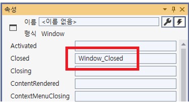
3.3 Window의 Closed 이벤트(Closed) 함수를 생성하여 Milmap 컨트롤 관련 메모리 해제와 scene 객체 메모리 해지를 위해 코드를 추가한다.
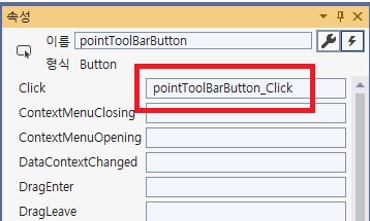
3.4 Scene 객체를 추가하기 위한 [Point], [Polyline], [Polygon], [Circle], [Symbol]을 선택한 뒤 [속성]창에서 각각 더블 클릭하여 Click 이벤트 함수를 추가한다.
pointToolBarButton의 경우 아래 그림과 같이 pointToolBarButton_Click 함수가 추가된다.
3.5 Scene 객체 추가 이벤트 함수에 nxSceneLayerEditor에 새로운 scene 객체를 생성하도록 요청하는 코드를 구현한다.
NXMilmapLayerSceneEditor의 CreateNewOBJ를 통해 매개변수에 따른 scene 객체를 생성하여 추가 및 편집 과정을 진행한다. CreatNewOBJ에 입력값은 scene 객체의 클래스 이름이다. Point, polyline, polygon, circle, symbol의 객체 추가 코드는 아래와 같다.
Toolbar의 “Polyline”을 선택한 후 프로그램의 Grid가 도시된 MilmapView에서 마우스 왼쪽 버튼을 클릭하고 마우스를 움직이면 생성된 Polyline을 확인할 수 있으며 2점 이상이 되면 “No named XscPolyLine” 이라는 이름과 함께 도시되는 것을 볼 수 있다.
정점을 추가하는 것은 마우스 왼쪽 버튼을 클릭하면 되고, 생성 작업을 종료하려면 마우스 왼쪽 버튼을 더블 클릭하면 된다. 생성작업을 종료하면 아래와 같이 객체의 정점 위치 조정, 크기 조정을 할 수 있는 컨트롤들을 확인할 수 있다.
각 객체는 기본 도시 속성정보를 이용하여 생성된다. Symbol의 경우,
을 기본값으로 하여 생성된다.
3.7 nxSceneLayerEditor에 OnObjectCreated 이벤트를 추가하여 XDL 엔진 내부에서 객체 생성 완료 시점에 각 객체에 대한 도시 속성을 변경해 본다.
nxSceneLayerEditor 생성자 다음에 아래와 같이 OnObjectCreated 이벤트를 추가한다.
C#
// MainWindow.xaml.cs

using Pixoneer.NXDL;
using Pixoneer.NXDL.NXMilmap;
using Pixoneer.NXDL.NSCENE;

namespace XDL_MilmapView3
{
    public partial class MainWindow : Window
    {
        private Pixoneer.NXDL.NSCENE.NXMilmapLayerSceneEditor nxSceneLayerEditor;
        private Pixoneer.NXDL.NSCENE.NXMilmapLayerSceneDisplay nxSceneLayerDisplay;
        public MainWindow()
        {
            InitializeComponent();
            nxSceneLayerDisplay = new NXMilmapLayerSceneDisplay();
            nxSceneLayerEditor = new NXMilmapLayerSceneEditor();
            nxSceneLayerEditor.OnObjectCreated += new NXSCEditEvent(nxSceneLayerEditor_OnObjectCreated);
        }
…
nxSceneLayerEditor_OnObjectCreated 함수에 아래와 같이 도시 속성 코드를 추가한다.
C#
bool nxSceneLayerEditor_OnObjectCreated(XscObj pObj)
{
    if (pObj == null) return false;

    // Scene 객체의 클래스 이름 가져오기
    string typeName = pObj.GetTypeName();
    if (typeName == "XscPoint")
    {
        XscPoint objPoint = (XscPoint)pObj;
        objPoint.LineColor = System.Drawing.Color.Yellow;
        // Point의 크기
        objPoint.LineWidth = 10;
        // PointType으로 Cross, Dot, Triangle, Rect, X가 있다.
        objPoint.PointType = XscPoint.ePointType.Rect;
        objPoint.Name = "Point #" + objPoint.ObjID.ToString();
    }
    else if (typeName == "XscPolyLine")
    {
        XscPolyLine objPolyLine = (XscPolyLine)pObj;
        objPolyLine.LineColor = System.Drawing.Color.LightGreen;
        objPolyLine.LinePattern = XscLinePattern.eLinePatternType.DashDot;
        objPolyLine.LineWidth = 3;
        objPolyLine.Name = "Polyline #" + objPolyLine.ObjID.ToString();
    }
    else if (typeName == "XscPolygon")
    {
        XscPolygon objPolygon = (XscPolygon)pObj;
        objPolygon.BorderColor = System.Drawing.Color.Blue;
        objPolygon.BorderSize = 3;
        objPolygon.LinePattern =
        XscLinePattern.eLinePatternType.DashDotDot;
        objPolygon.FillColor = System.Drawing.Color.Cyan;

        // FillPattern이 Solid가 아닌 경우에는 배경색이 투명하게 처리된다.
        objPolygon.FillPattern = XscFillPattern.eFillPatternType.Cross;
        objPolygon.Name = "Polygon #" + objPolygon.ObjID.ToString();
    }
    else if (typeName == "XscCircle")
    {
        XscCircle objCircle = (XscCircle)pObj;
        objCircle.LineColor = System.Drawing.Color.Coral;
        objCircle.LineWidth = 2;
        objCircle.FillColor = System.Drawing.Color.GreenYellow;
        objCircle.FillPattern = XscFillPattern.eFillPatternType.Vertical;
        objCircle.Name = "Circle #" + objCircle.ObjID.ToString();
    }
    else if (typeName == "XscSymbol")
    {
        XscSymbol objSymbol = (XscSymbol)pObj;

        // DefaultSymbolName으로 사용할 수 있는 것은 Apartment, Image, Model, Public, Stadium, TextChart가 있다.
        // 이는 XDL 엔진 설치 폴더 중 Resource\Scenes\Icons에 저장되어 있다.
        // 사용자 정의의 심볼을 로딩하고자 한다면, DefaultSymbolName 대신 UserSymbolPath 속성으로 경로를 설정한다.
        objSymbol.DefaultSymbolName = "Apartment";
        objSymbol.UpdateSymbol();
        objSymbol.Name = "Symbol #" + objSymbol.ObjID.ToString();
    }

    nxMilmapView1.RefreshScreen();
    return default(bool);
}
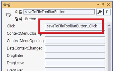
3.8 nxMilmapView1에 생성한 scene 객체를 파일로 저장하기 위해 [Save To File]의 [속성]창에서 더블 클릭하여 이벤트함수를 추가하고 코드를 구현한다.
마우스로 더블 클릭하면 “Click”에 대한 이벤트 함수가 자동 추가된다.
nxSceneEditor의 XScene 객체를 얻어 파일로 저장한다. XDL 엔진의 Scene 파일은 SML을 확장자로 하는 XML 파일이다. 코드는 아래와 같다.
C#
private void saveToFileToolBarButton_Click(object sender, RoutedEventArgs e)
{
    // 생성한 scene 객체를 가지고 있는 최상위 XScene 객체를 얻어온다.
    XScene sceneRoot = nxSceneLayerEditor.GetScene();
    if (sceneRoot == null) return;

    // 저장을 위한 FileDialog 생성
    SaveFileDialog saveDlg = new SaveFileDialog();
    saveDlg.Filter = "XDL Scene file(*.sml)|*.sml;||";
    Nullable<bool> result = saveDlg.ShowDialog();
    if (result != true) return;

    // 파일경로에 XScene 객체의 데이터를 XML 형태로 저장한다.
    // 세 번째 매개변수인 XSpatialReference는 출력 좌표계 정보를 설정하는 것으로서 여기에서는 XScene 객체의 좌표계 정보로 하겠다.
    if (XScene.SaveScene(sceneRoot, saveDlg.FileName, sceneRoot.SR))
    {
        MessageBox.Show("MilmapView의 scene 객체를 파일로 저장하였습니다.");
    }
    else
    {
        MessageBox.Show("MilmapView의 scene 객체를 파일로 저장하지 못했습니다.");
    }
}
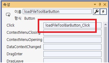
3.9 Scene 파일인 SML 파일을 선택하여 scene 객체를 생성하지 않은 다른 MilmapView 환경에 도시하도록 한다. 이를 위한 [Load into MilmapView2]의 [속성]창에서 더블 클릭하여 Click 이벤트함수를 추가하고 파일을 로딩하는 코드를 추가한다.
마우스로 더블 클릭하면 “Click”에 대한 이벤트 함수가 자동 추가된다.
SML 파일을 NXMilmapLayerSceneDispaly의 Open 함수 이용하여 로딩하면 NXMilmapLayerSceneDisplay의 scene 데이터가 파일의 내용으로 갱신된다. 본 예제에서는 NXMilmapLayerSceneDisplay 변수인 nxSceneLayerDisplay의 Open 함수를 통해 SML 파일을 로딩한 후 XScene 객체를 얻어서 도시
순서를 설정한다.
XScene에 추가된 scene 객체를 추가된 순서대로 도시하고자 하면, XScene 객체를 얻어 DisplayOrder를 OrderByAddSequence로 수정한다. XScene의 DisplayOrder 기본값은 OrderNone으로, OrderNone, OrderByAddSequence, OrderByUserSequence가 있다.
코드는 아래와 같다.
C#
private void loadFileToolBarButton_Click(object sender, RoutedEventArgs e)
{
    // 파일을 선택하기 위해서 FIleDialog 생성
    OpenFileDialog openDlg = new OpenFileDialog();
    openDlg.Filter = "XDL Scene file(*.sml)|*.sml;||";
    Nullable<bool> result = openDlg.ShowDialog();
    if (result != true) return;

    // NXPlanetLayerSceneDisPlay의 Open함수를 이용하여 scene 객체 로딩
    if (nxSceneLayerDisplay.Open(openDlg.FileName))
    {
        XScene scene = nxSceneLayerDisplay.GetScene();
        // XSene 객체 도시 방법을 추가되는 순서대로 도시하도록 설정한다.
        // 기본값은 XScene.eDisplayOrder.OrderNone이다.
        scene.DisplayOrder = XScene.eDisplayOrder.OrderByAddSequence;

        MessageBox.Show("MilmapView의 scene 객체를 갱신하겠습니다.");
    }
    else
    {
        MessageBox.Show("scene 파일을 로딩할 수 없습니다");
    }
}

 프로젝트 속성 설정 : XDL 시작하기 중
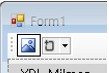
 버튼을 클릭하여 ToolStripButton을 추가하며
  아이콘이 추가된다.

 을 기본값으로 하여 생성된다.